ARTICLE
Overcoming Key Challenges in Helical Pile Installation for Solar Farms
Summary
- Geotechnical Investigation is Key: Success starts with a thorough geotechnical investigation. Understanding Australia’s diverse soil conditions, from reactive clays to sandy profiles, is the first step to mitigating installation risks.
- Installation Issues are Manageable: Common challenges like pile refusal, achieving correct installation torque requirements, and maintaining pile alignment can be overcome with proper planning, specialised installation equipment, and experienced crews.
- Design Must Match Conditions: Helical pile design for solar arrays is not one-size-fits-all. Pile depth, helix configuration, and corrosion protection must be tailored to site-specific data to ensure long-term performance.
- Compliance is Non-Negotiable: Adherence to Australian standards for helical piles, including AS 2159, is essential for the structural integrity and compliance of any solar farm construction project.
Helical piles are increasingly the foundation solution of choice for commercial and utility-scale solar farms Australia-wide.
Their rapid installation, minimal site disturbance, and immediate load-bearing capacity offer significant advantages over traditional concrete foundations, optimising project timelines.
For engineers, designing and specifying these systems requires a clear understanding of the potential installation challenges.
This article addresses the primary geotechnical challenges and practical on-site issues encountered during the installation of helical piles for solar projects, providing engineers with actionable insights for ensuring foundation success.
The Critical Role of Geotechnical Investigations
A successful installation hinges on the quality of the upfront geotechnical investigation.
Without a comprehensive understanding of the subsurface conditions, engineers risk specifying a foundation system that is either over-engineered and costly or, more seriously, under-engineered and prone to failure.
This initial phase is the most valuable investment in risk mitigation for any renewable energy infrastructure project.
Understanding Australia’s Diverse Soil Profiles
Australia presents a vast and varied geological landscape. The soil conditions for helical piles can change dramatically not just between regions but across a single project site.
For example, a solar farm in Victoria may contend with highly reactive clays that shrink and swell with moisture changes, exerting significant uplift or down-drag forces on piles.
In contrast, a project in Western Australia might be founded on loose, sandy soils that offer poor frictional resistance, or encounter hardpan calcrete layers that can cause premature refusal.
Understanding these profiles is fundamental. A design specified for the clay plains of New South Wales will likely be unsuitable for the rocky ground often found in Queensland.
A detailed soil testing program is the only way to accurately characterise the site and inform a robust foundation design.
| Australian Soil Classification (AS 2870) | Description | Helical Pile Installation Challenge | Potential Solution |
|---|---|---|---|
| Class A | Mostly sand and rock sites, little or no ground movement | Low risk | Standard pile design and configuration |
| Class S | Slightly reactive clay sites, slight ground movement | Minor difficulty achieving consistent torque readings | Minor adjustments to helix pitch or diameter |
| Class M | Moderately reactive clay sites, moderate ground movement | Potential for torque variability, seasonal movement effects on piles | Deeper pile embedment below the zone of seasonal moisture change |
| Class H1/H2 | Highly reactive clay sites, high to very high ground movement | Significant uplift/down-drag forces, installation refusal in dry, hard clay | Deeper embedment, void formers to isolate shaft from reactive soil |
| Class E | Extremely reactive sites, extreme ground movement | High risk of long-term pile instability and structural failure | May require ground improvement or alternative foundation systems |
| Class P | Problem sites (e.g., soft soils, fill, loose sands, mine-subsidence) | Low lateral and/or vertical capacity, insufficient torque achieved | Grouting, larger/more helices, ground compaction before installation |
Interpreting Geotechnical Data for Pile Design
The geotechnical report is the foundational blueprint for the pile design. Data from Standard Penetration Tests (SPT) or Cone Penetration Tests (CPT) provides the critical information needed to perform the necessary civil engineering calculations.
This data helps determine the appropriate pile length, shaft diameter, and the number and size of the helices. Engineers use this information to calculate the required installation torque, which serves as a direct field measurement of the pile’s ultimate capacity.
Overlooking subtle soil strata changes in the report or failing to plan for variability across a large site can lead to widespread installation issues, significant delays, and costly on-the-fly redesigns.
Common Installation Challenges and On-Site Solutions
Even with a thorough geotechnical report, on-site conditions can present unexpected challenges. A proactive approach and an experienced installation team are vital for addressing these issues efficiently.
Navigating Unexpected Ground Refusal
Pile refusal occurs when the pile can no longer be advanced to its designed embedment depth. This is often caused by encountering unforeseen obstructions like rock floaters, boulders, or an exceptionally dense soil layer that was not detected during the initial, limited borehole investigation.
Refusal is a significant problem because a pile that does not reach its target depth will not have the required uplift resistance or lateral load capacity to support the solar panel ground mounting systems.
When refusal is encountered, the following steps should be taken:
- Step 1: The machine operator must immediately stop applying torque and downward pressure to avoid damaging the pile shaft or the drive head.
- Step 2: The refusal depth is recorded and compared against the design depth and the nearest borehole log to try and identify the cause.
- Step 3: A common first attempt is to pre-drill the pile location with an auger to break through the obstruction.
- Step 4: If pre-drilling is unsuccessful, the pile location may be offset by a small distance (typically 300-600mm), provided this does not conflict with the solar array layout.
- Step 5: If refusal is a widespread issue across the site, it points to a discrepancy between the geotechnical report and actual conditions. At this point, the project engineer must be consulted to revise the pile design, potentially specifying a shorter, larger-diameter pile or one with a different helix configuration to achieve capacity in the upper, competent soil layers.
Achieving and Verifying Installation Torque
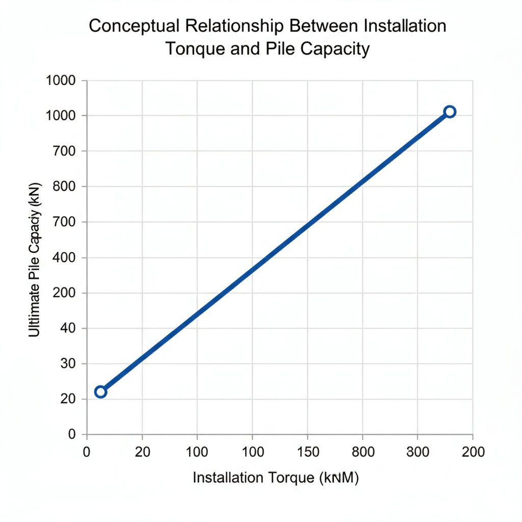
The relationship between installation torque and pile capacity is a core principle of helical pile engineering. The energy (torque) required to screw the pile into the ground is empirically correlated to its ultimate load-bearing capacity.
The challenge lies in achieving the specified target torque. In soft clays or loose sands, the pile may “spin out,” where the helices churn the soil instead of advancing, and the target torque is never reached. This indicates that the pile will not have the required capacity.
In very dense sands or hard clays, the torque required can exceed the structural limits of the pile shaft or the capacity of the installation equipment. Real-time torque monitoring is therefore essential.
Digital torque transducers integrated into the drive head provide the operator and quality assurance team with a precise reading for every pile installed.
If torque is not being met, solutions include advancing the pile deeper into a more competent stratum, or replacing it with a pile that has larger or additional helices to increase the bearing surface area.
Managing Pile Alignment and Verticality
Solar panel ground mounting systems are manufactured with precise tolerances. The foundations they connect to must be installed with the same precision. Helical piles must be installed within strict tolerances for verticality (plumbness) and location.
Deviations can create major issues during the racking installation phase, leading to delays and costly rework. The main causes of misalignment are sloped terrain, buried obstructions that deflect the pile shaft, and improper equipment setup.
To manage this, experienced operators use drive heads equipped with inclinometers and work from clear survey set-out points. Maintaining a slow, consistent rate of installation helps ensure the pile advances straight into the ground.
Selecting the Right Installation Equipment
The choice of installation equipment is dictated by the geotechnical challenges and site conditions.
For large, open sites with competent soils, high-capacity excavators (20-30 tonnes) fitted with high-torque hydraulic drive heads are efficient. For sites with difficult access, steep terrain, or sensitive environmental constraints, smaller, specialised tracked machines may be required.
The equipment must be capable of delivering the necessary torque to install the piles to the design requirements. Under-powered equipment is a common cause of project delays and helical pier installation problems.
Mobilising and maintaining this heavy machinery in remote parts of Australia adds another layer of logistical complexity that must be factored into the project timeline.
Corrosion Protection in Aggressive Environments
A solar farm is a long-term asset, and its foundations must be designed for durability over several decades. Corrosion protection is therefore a primary concern, especially in Australia’s varied and sometimes aggressive environments.
Coastal sites with high salinity or inland areas with acidic or sulphate-rich soils can accelerate steel corrosion. The minimum standard for corrosion protection is hot-dip galvanisation in accordance with AS/NZS 4680.
For more aggressive soil environments, identified through soil resistivity and pH testing, a geotechnical or corrosion engineer may specify a greater galvanising thickness, a larger steel section to provide a sacrificial corrosion allowance, or the addition of cathodic protection systems.
Ensuring Compliance with Australian Standards
Navigating the regulatory landscape is an essential part of the engineering process. For helical piles, the primary document is AS 2159-2009, Piling – Design and Installation.
This standard sets out the minimum requirements for design, installation, and testing to ensure foundation systems are safe and fit for purpose. It covers aspects such as load testing protocols, material specifications, and safety considerations during installation.
Alongside AS 2159, designs must also conform to the National Construction Code (NCC) and other relevant structural steel and welding standards.
Working with an installation partner who has a deep understanding of these Australian standards for helical piles is vital for ensuring project compliance and de-risking the project for all stakeholders.
On Overcoming Helical Pile Installation Challenges
The installation of helical piles for solar projects in Australia presents unique challenges, primarily driven by the continent’s diverse soil conditions. Issues such as ground refusal, torque verification, and alignment require diligent engineering and experienced field execution.
However, these challenges are entirely manageable through a disciplined process that prioritises thorough geotechnical investigation, robust helical pile design, and the use of appropriate installation equipment.
By anticipating these problems and partnering with specialists versed in Australian standards, engineers can confidently specify helical piles as a rapid, reliable, and cost-effective foundation solution for the nation’s growing renewable energy sector.
Frequently Asked Questions About Helical Pile Installation for Solar
What Are the Disadvantages of Helical Piles?
The main disadvantages relate to ground conditions. Helical piles are not ideal for sites with dense layers of cobbles, boulders, or shallow bedrock, which can cause premature pile refusal. They can also be challenging to install in un-compacted or very soft, organic soils where achieving the required installation torque requirements for capacity is difficult. A detailed geotechnical investigation is essential to determine their suitability.
How Deep Do Helical Piles Need To Be for Solar Panels?
The depth is entirely site-specific and determined by the geotechnical investigation. Piles must be embedded deep enough to engage a soil stratum capable of providing the required uplift resistance and bearing capacity. In Australia, this can range from as shallow as 3 metres in dense soils to over 10 metres in softer or more problematic profiles. The depth must also be sufficient to bypass any active zones in reactive clay soils.
What Is the Failure of Helical Piles?
Helical pile failure can occur in several ways. Structural failure involves the physical yielding or buckling of the steel shaft due to excessive torque or load. Geotechnical failure occurs when the soil around the helices cannot provide the required resistance, leading to the pile settling (compression failure) or pulling out (uplift failure). Lateral failure can also occur if the pile cannot resist horizontal forces from wind on the solar arrays.
What Are the Problems With Screw Piles?
The problems with screw piles (a term often used interchangeably with helical piles in Australia) are typically installation-related. The most common solar pile driving issues include hitting obstructions (pile refusal), failing to reach the design torque in soft ground, and corrosion if the protective coating (usually galvanisation) is damaged during installation or is inadequate for the aggressiveness of the soil.
What Is the Difference Between a Screw Pile and a Helical Pile?
In Australia, the terms “screw pile” and “helical pile” are generally used interchangeably to describe a steel foundation with one or more helical plates welded to a central shaft. Historically, some distinctions were made based on manufacturing processes, but today they refer to the same product. The key components are the steel shaft, the helices, and the connection for the drive head.
Are Helical Piles Suitable for All Soil Types?
Helical piles are suitable for a very wide range of soil conditions, including clays, silts, sands, and gravels. They are particularly effective in soils where traditional foundations are difficult. However, they are not a universal solution. Their performance is limited in soils with large boulders or cobbles, on sites with shallow, hard bedrock, or in soils that are too soft to generate the necessary torque-to-capacity relationship.
Need a quote or more info? Start here.
Contact Us
info@helicalpilesaustralia.com.au
+61 2 7251 9258
Mon–Fri, 8:00am–5:00pm AEST
Built for complexity.
Engineered for certainty.
A trusted partner for large-scale energy and infrastructure projects where precision isn’t optional, it’s mandatory

Engineered foundation systems for energy and infrastructure across Australia.
© 2026 Helical Piles Australia. All rights reserved.
Privacy Policy
Contact Us
info@helicalpilesaustralia.com.au
+61 2 7251 9258
Mon – Fri, 8:00am – 5:00pm AEST
Location
223 Liverpool Street
Darlinghurst, NSW 2010